RF Dummy Loads
High Power Dummy Loads are indispensable solutions for industries demanding precise RF testing, heat dissipation, and signal integrity validation. RF dummy loads are an essential tool in the broadcasting industry because they allow broadcasters to test and tune their equipment without emitting unwanted RF signals. When transmitting equipment is tested, it is important to ensure that the transmitted signal is transmitted only to the intended receivers and not out into the environment where it can cause interference with other radio signals. Some synonyms for RF dummy load include: RF load, dummy load, impedance load, RF termination, load resistor, coaxial terminator, RF test load, radio frequency terminator, RF absorber, and signal attenuator.
1. Unleash Superior Performance: The Critical Role of High Power Dummy Loads
At FMUSER, we specialize in designing robust RF components tailored to simplify complex workflows. This page organizes our solutions by power ratings, frequency ranges, and application-specific designs, empowering professionals in telecom, aerospace, and broadcasting to find the perfect match for their testing needs.
2. Powerful Innovations: Engineered for Peak Performance
- Military-Grade Durability: Built to withstand extreme temperatures (up to 200°C) and continuous operation.
- Certified Precision: Compliant with CE/FCC standards for accurate, repeatable RF testing.
- Advanced Thermal Management: Patented heat dissipation technology ensures stability even at 10kW+ loads.
- Scalable Solutions: From 50W entry-level units for hobbyists to 50kW industrial systems for enterprise use.
3. Transformative Applications: Where FMUSER’s Solutions Shine
- RF Transmitter Testing: Validate transmitter output without radiation risks. FMUSER’s loads handle up to 50GHz, ideal for 5G/6G mobile base stations.
- Broadcast System Calibration: Ensure signal clarity in FM/AM transmitters. Water-cooled designs maintain stability during 24/7 operation.
- Military & Aerospace Testing: Ruggedized units survive harsh environments, perfect for radar and satellite equipment validation.
- Telecom Infrastructure Protection: Prevent overload damage in cellular networks with rapidly deployable, high-attenuation loads.
4. Why FMUSER? Your Trusted Partner in RF Excellence
- Factory-Direct Pricing: Save 30%+ compared to distributors.
- Fast Global Shipping: In-stock units delivered in 3–5 business days.
- Turnkey Packages: Includes cooling systems, meters, and mounting hardware.
- Pre-Configured or Custom: OEM-friendly designs with 24-hour technical support.
- Proven Expertise: Trusted by Ericsson, NASA, and global broadcasters.
5. Smarter Selection: A Buyer’s Checklist for Optimal ROI
- Power Requirements (50W–50kW options).
- Frequency Compatibility (DC–50GHz).
- Cooling Needs (air, water, or oil-based).
- Budget Range (entry-level to bespoke industrial systems).
-
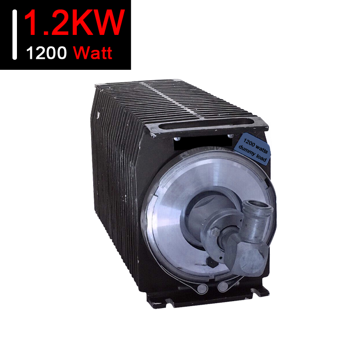
![1.2KW RF Dummy Load RF Load 1.2KW RF Termination 1200 Watt Attenuator for Sale]()
1.2KW RF Dummy Load RF Load 1.2KW RF Termination 1200 Watt Attenuator for Sale
Price(USD):Ask for a quotation
Sold:18
-
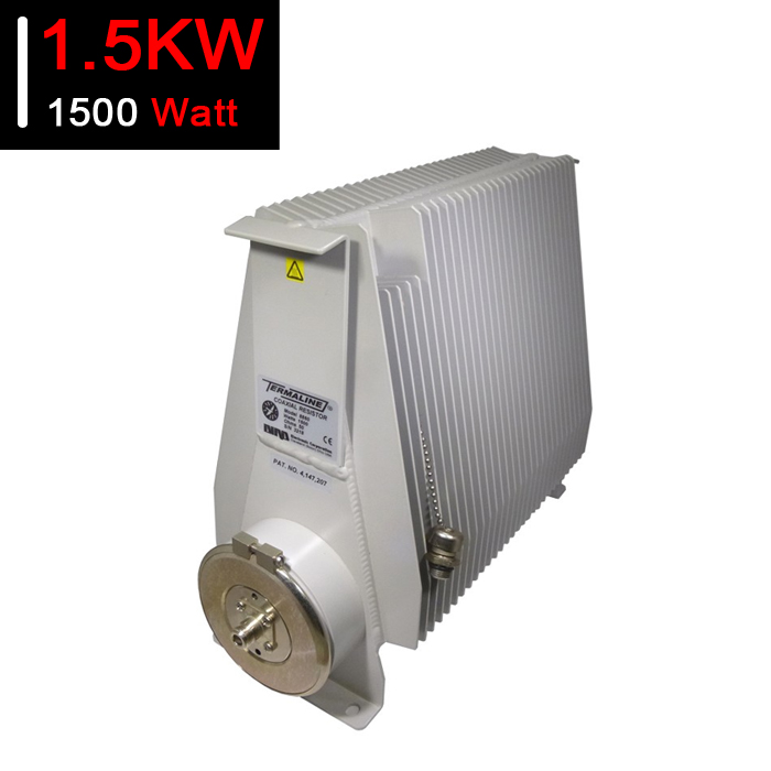
![1.5KW RF Dummy Load RF Load 1.5KW RF Termination 1500 Watt Attenuator for Sale]()
1.5KW RF Dummy Load RF Load 1.5KW RF Termination 1500 Watt Attenuator for Sale
Price(USD):Ask for a quotation
Sold:41
-
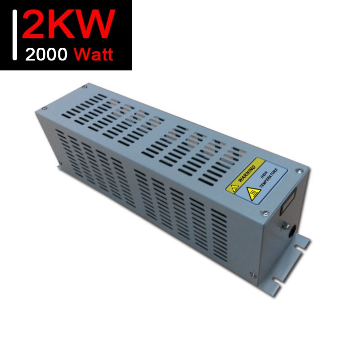
![2KW RF Dummy Load RF Load 2KW RF Termination 2000 Watt Attenuator for Sale]()
2KW RF Dummy Load RF Load 2KW RF Termination 2000 Watt Attenuator for Sale
Price(USD):Ask for a quotation
Sold:31
-
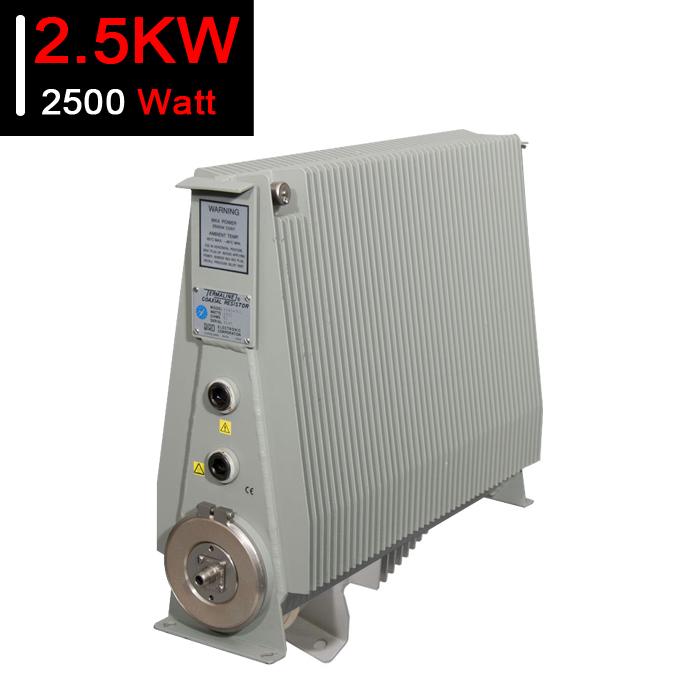
![2.5KW RF Dummy Load RF Load 2.5KW RF Termination 2500 Watt Attenuator for Sale]()
2.5KW RF Dummy Load RF Load 2.5KW RF Termination 2500 Watt Attenuator for Sale
Price(USD):Ask for a quotation
Sold:25
-
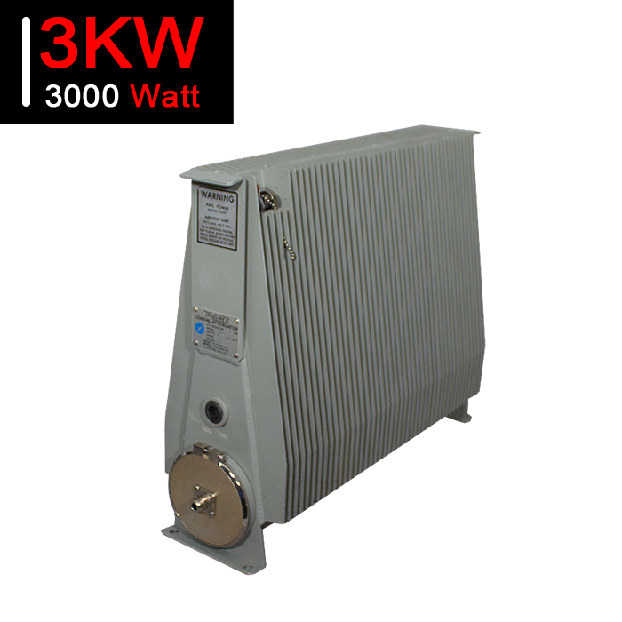
![3KW RF Dummy Load RF Load 3KW RF Termination 1000 Watt Attenuator for Sale]()
3KW RF Dummy Load RF Load 3KW RF Termination 1000 Watt Attenuator for Sale
Price(USD):Ask for a quotation
Sold:15
-
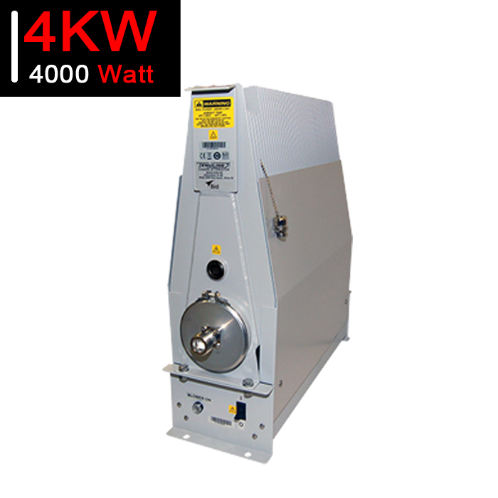
![4KW RF Dummy Load RF Load 4KW RF Termination 4000 Watt Attenuator for Sale]()
4KW RF Dummy Load RF Load 4KW RF Termination 4000 Watt Attenuator for Sale
Price(USD):Ask for a quotation
Sold:17
-
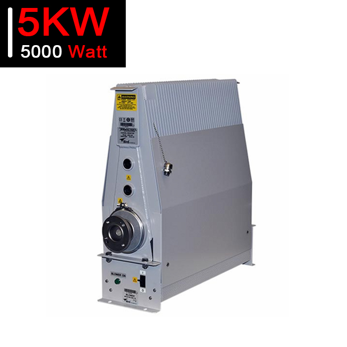
![5KW RF Dummy Load RF Load 5KW RF Termination 5000 Watt Attenuator for Sale]()
5KW RF Dummy Load RF Load 5KW RF Termination 5000 Watt Attenuator for Sale
Price(USD):Ask for a quotation
Sold:17
-
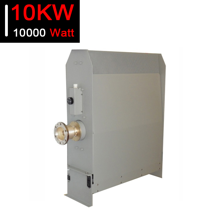
![10KW RF Dummy Load RF Load 10KW RF Termination 10000 Watt Attenuator for Sale]()
10KW RF Dummy Load RF Load 10KW RF Termination 10000 Watt Attenuator for Sale
Price(USD):Ask for a quotation
Sold:17
-
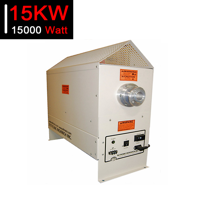
![15KW RF Dummy Load RF Load 15KW RF Termination 10000 Watt Attenuator for Sale]()
15KW RF Dummy Load RF Load 15KW RF Termination 10000 Watt Attenuator for Sale
Price(USD):Ask for a quotation
Sold:13
-
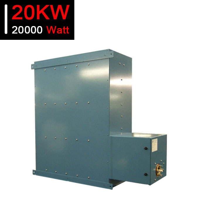
![20KW RF Dummy Load RF Load 20KW RF Termination 20000 Watt Attenuator for Sale]()
20KW RF Dummy Load RF Load 20KW RF Termination 20000 Watt Attenuator for Sale
Price(USD):Ask for a quotation
Sold:14
-
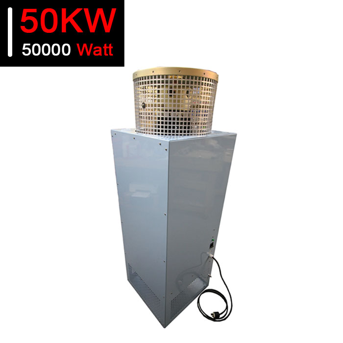
![50KW RF Dummy Load RF Load 50KW RF Termination 50000 Watt Attenuator for Sale]()
50KW RF Dummy Load RF Load 50KW RF Termination 50000 Watt Attenuator for Sale
Price(USD):Ask for a quotation
Sold:9
-
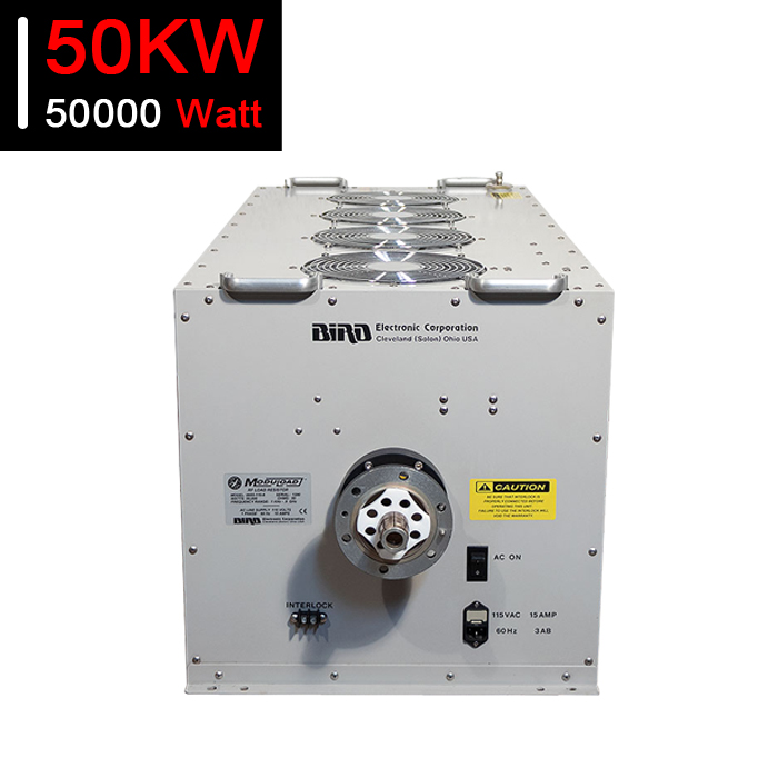
![50KW RF Dummy Load RF Load 50KW RF Termination 50000 Watt Attenuator for Sale]()
50KW RF Dummy Load RF Load 50KW RF Termination 50000 Watt Attenuator for Sale
Price(USD):Ask for a quotation
Sold:35
-
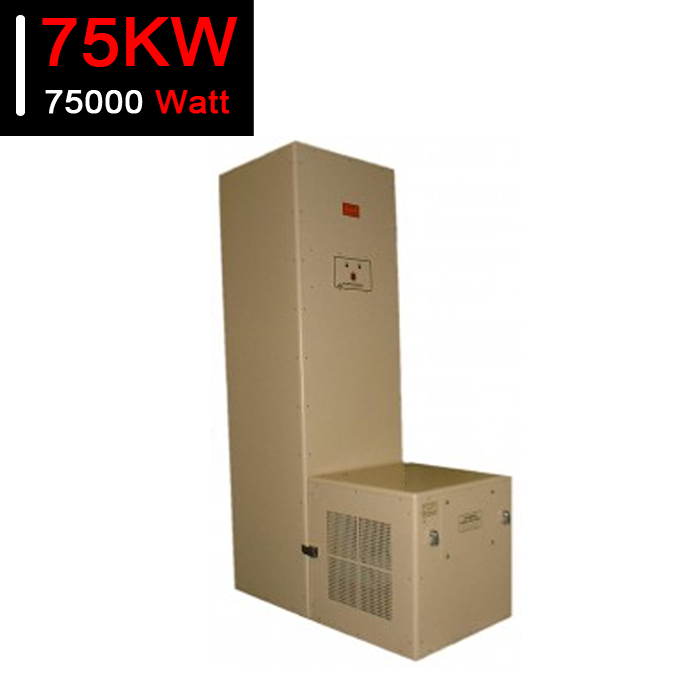
![75KW RF Dummy Load RF Load 50KW RF Termination 75000 Watt Attenuator for Sale]()
75KW RF Dummy Load RF Load 50KW RF Termination 75000 Watt Attenuator for Sale
Price(USD):Ask for a quotation
Sold:4
-
![100KW RF Dummy Load RF Load 100KW RF Termination 100000 Watt Attenuator for Sale]()
100KW RF Dummy Load RF Load 100KW RF Termination 100000 Watt Attenuator for Sale
Price(USD):Ask for a quotation
Sold:3
-
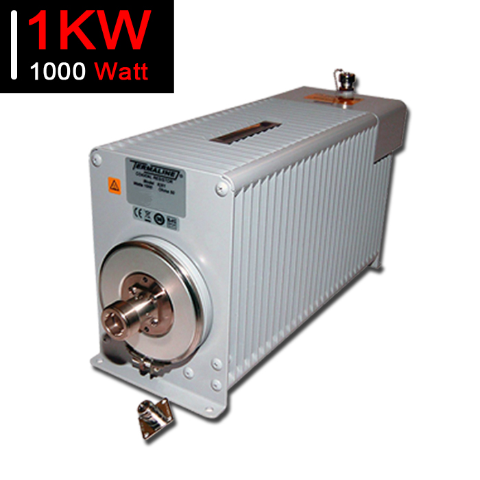
![1KW RF Dummy Load RF Load 1KW RF Termination 1000 Watt Attenuator for Sale]()
1KW RF Dummy Load RF Load 1KW RF Termination 1000 Watt Attenuator for Sale
Price(USD):Ask for a quotation
Sold:54
-
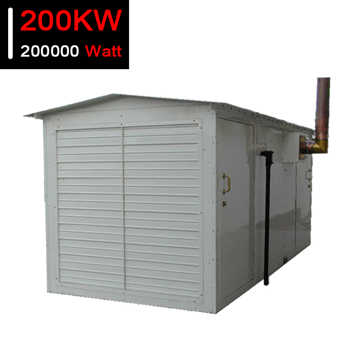
![200KW RF Dummy Load RF Load 200KW RF Termination 100000 Watt Attenuator for Sale]()
200KW RF Dummy Load RF Load 200KW RF Termination 100000 Watt Attenuator for Sale
Price(USD):Please Contact Us
Sold:2
- What else equipment are used along with a RF dummy load when broadcasting?
- When broadcasting, there are a number of pieces of equipment that are used alongside an RF dummy load. Here are some of the most common components:
1. Transmitter: The transmitter is the heart of the broadcasting system. It generates the radio frequency signal that is transmitted over the airwaves, and it is connected to the RF dummy load during testing and tuning.
2. Antenna: The antenna is the component that radiates the RF signal into the environment. It is connected to the transmitter and is positioned to best propagate the signal to the intended listeners.
3. RF filter: RF filters are used to clean up the signal before it is sent to the antenna, removing any unwanted frequencies or interference that may have been introduced during the modulation process.
4. RF amplifier: RF amplifiers are used to boost the power of the RF signal. In broadcasting, RF amplifiers are often used to increase the signal strength so that it can reach a wider audience.
5. Modulator: The modulator is responsible for encoding the audio signal onto the radio frequency carrier signal. It is used to vary the amplitude, frequency, or phase of the carrier signal in response to the audio signal.
6. Audio processing equipment: Audio processing equipment is used to enhance the clarity, loudness, and other qualities of the audio signal before it is modulated onto the RF carrier signal.
7. Power supply: The power supply provides the necessary electrical power to operate the broadcasting equipment.
All of these pieces of equipment work together to create a high-quality, clear broadcast signal that can reach a wide audience. The RF dummy load is a critical component in this process, as it allows for safe and accurate testing and tuning of the broadcasting equipment without transmitting unwanted RF signals into the environment.
- What are common types of RF dummy load used for radio broadcasting?
- There are several types of RF dummy loads available, each with its own unique design and purpose. Here is an overview of some of the most common types:
1. Wire-wound Dummy Load: This type of dummy load is made of precision wire wound into a coil, and it is typically used for low power applications. It offers good cooling due to its open structure, but it can suffer from problems with inductance and capacitance at higher frequencies.
2. Carbon Composite Dummy Load: This type of dummy load is made of a composite material containing carbon and other materials. It offers good heat dissipation and power handling capacity, but it can be more expensive than other types.
3. Air-Cooled Dummy Load: This is a simple, low-cost type of dummy load that uses air flow to cool the resistive element. It is typically used for low power applications, and it can be noisy and prone to overheating.
4. Oil-Cooled Dummy Load: This type of dummy load uses oil to cool the resistive element, offering better heat dissipation than air-cooled models. It is typically used for higher power applications but can be difficult to maintain and repair.
5. Waveguide Dummy Load: Waveguide dummy loads are designed to terminate waveguide structures and are typically used in high-power microwave applications. They are specialized devices that are designed for a specific frequency range, and they can be expensive.
6. Fan-Cooled Dummy Load: Fan-cooled dummy loads use a fan to cool the resistive element, offering good cooling and power handling capacity. They are typically used for medium power applications and can be more expensive than air-cooled models.
In summary, the type of RF dummy load used depends on the application requirements, such as power handling capacity, frequency range, cooling method, and cost. Wire-wound dummy loads are typically used for low power applications, while oil-cooled and fan-cooled models are better for medium to high power applications. Waveguide dummy loads are specialized devices used for specific frequency ranges, while air-cooled models are simple, low-cost options for low power applications. The cost of these RF dummy loads varies depending on the type, with more specialized or high-performance models being more expensive. Installation of these devices typically involves connecting them to the proper equipment, while maintenance and repair can include replacing damaged resistive elements or cooling systems.
- What differs a small and large RF dummy load?
- The main differences between a small RF dummy load and a large RF dummy load are in their structures, cooling methods, power handling capacity, and applications. Here is a more detailed comparison:
Structure:
Small RF dummy loads typically have a compact size and are designed to handle lower power levels. They may have a wire-wound or carbon composite structure and use air or liquid cooling. Large RF dummy loads, on the other hand, are much larger in size and are capable of handling much higher power levels. They often use oil or a water-cooled system and have a more robust structure.
Advantages:
Small RF dummy loads have the advantage of being compact and less expensive than large dummy loads. They are also easier to handle and transport. Large RF dummy loads, on the other hand, can handle much higher power levels and are suitable for high-power applications such as broadcasting or industrial RF testing.
Disadvantages:
The disadvantages of small RF dummy loads are their limited power handling capacity and lower tolerance to frequency changes. Large RF dummy loads are much more expensive, very large in size, and require more maintenance.
Power handling capacity:
Small RF dummy loads can only handle a limited amount of power, usually only a few watts or milliwatts. Large RF dummy loads, on the other hand, can handle much higher power levels, up to hundreds of kilowatts.
Cooling method:
The cooling method for small RF dummy loads is typically air or liquid-based, while large RF dummy loads often use oil or a water-cooled system.
Prices:
Small RF dummy loads are generally less expensive than large RF dummy loads, due to their smaller size and lower power handling capacity.
Applications:
Small RF dummy loads are often used for laboratory and testing applications, while large RF dummy loads are used in broadcasting, industrial testing, or where high power loads are required.
Size:
Small RF dummy loads are usually compact in size, while large RF dummy loads can be very large and require a significant amount of space.
Performance:
Small RF dummy loads are more susceptible to performance issues caused by changes in frequency, while large RF dummy loads are designed for heavy-duty operations and are much more reliable.
Frequency:
Small RF dummy loads are usually limited to specific frequency ranges, while large RF dummy loads can handle a wide range of frequencies.
Installation and maintenance:
The installation of small RF dummy loads is usually straightforward and simple. However, large RF dummy loads require specialized installation and maintenance due to their more complex structure and cooling systems.
In summary, small RF dummy loads are typically used for laboratory and testing applications due to their compact size and affordability, while large RF dummy loads are used in broadcasting and industrial testing due to their high power handling capacity and more robust structure. Small RF dummy loads typically use air or liquid cooling, while large RF dummy loads use oil or water-cooled systems.
- How RF dummy loads are used in actual scenes?
- RF dummy loads have a wide range of applications in different fields of electronics and communications. Here are some of the common applications of RF dummy loads:
1. Testing and calibration: RF dummy loads are often used in testing and calibration of RF equipment, such as transmitters, amplifiers, and receivers. They provide a non-radiating load that is crucial for testing equipment without interfering with other communication devices.
2. Matching networks: RF dummy loads can be used as matching networks for testing RF power amplifier stages. They provide a resistive load that can match the impedance of the amplifier, making it possible to test its performance accurately.
3. Troubleshooting: RF dummy loads can also be used in troubleshooting and fault finding of RF equipment. By temporarily replacing the antenna with a dummy load, engineers can verify if a fault occurs within the transmitter or receiving equipment.
4. Broadcast stations: In broadcast stations, RF dummy loads are typically used during testing and maintenance of transmitting equipment. They help to isolate the station's generator and transmitter from the antenna while maintaining the correct impedance match.
5. Industrial testing: RF dummy loads are used in industrial testing of radio frequency equipment, such as testing antennas, filters, and waveguides.
6. Medical imaging: RF dummy loads are used in medical imaging equipment, such as MRI scanners, to absorb the RF power that is not absorbed by the human body. This helps to prevent unwanted radiation exposure to the patient and healthcare workers.
7. Military applications: RF dummy loads are used in military applications, such as testing communication systems, radar, and electronic warfare equipments. They help to ensure the proper operation of these systems while preventing unwanted RF emissions that may compromise the military's position.
8. Ham radio operators: RF dummy loads are commonly used by ham radio operators for testing and adjusting their radio equipment. They can help to ensure that the radio is operating correctly before making any transmissions.
9. Education and training: RF dummy loads are useful in educational and training settings for learning about the proper operation and maintenance of RF equipment. They can also be used to demonstrate RF theory and to learn about testing and calibration techniques.
10. Amateur rocketry: RF dummy loads are sometimes used in amateur rocketry to ground test igniters and electrical systems before launch. This can help to ensure the safety and effectiveness of the launch.
11. Aerospace testing: RF dummy loads can be used in aerospace testing to simulate the impedance of antennas and other RF equipment. This helps to ensure the proper operation of the equipment in different environments.
12. Research and development: RF dummy loads are used in research and development to test the performance of new RF equipment and technologies. They can help to identify the potential for RF interference, inefficiency, or other issues that may arise.
In summary, RF dummy loads have numerous applications in different fields of electronics and communications. They are commonly used for testing and calibration of RF equipment, troubleshooting, matching networks, broadcast stations, industrial testing, medical imaging, and military applications, etc.
- Apart from a dummy load, what else equipment are used to build up a broadcasting system?
- Building a complete radio braodcasting system for a broadcasting station requires more than just an RF dummy load. Here are the typical components needed for a complete radio broadcasting system:
1. Antenna tower: A tower is needed to mount the antenna at a sufficiently high elevation to ensure a wide coverage area.
2. Antenna: The antenna is responsible for radiating the broadcast signal into the surrounding area. Different types of antennas are used depending on the frequency band and broadcast type.
3. Transmission line: A transmission line is used to connect the transmitter to the antenna. The transmission line needs to be carefully chosen to minimize loss over the required distance.
4. Transmitter: The transmitter generates the RF signal that is sent to the antenna. The transmitter needs to be operated within the specifications of the antenna and transmission line to avoid damage.
5. Antenna tuner: An antenna tuner may be required to match the impedance of the transmitter to the impedance of the antenna for optimal performance.
6. Lightning protection: Lightning can cause damage to the transmission line, tower, and other components of the antenna system. Surge suppressors and other lightning protection devices are typically used to prevent damage.
7. Grounding system: A grounding system is needed to protect against lightning strikes, static discharge, and other electrical events. The grounding system must be designed and installed to minimize interference with the operation of the antenna system.
8. Remote control and monitoring system: A remote control and monitoring system is used to remotely monitor and control the performance of the antenna system, including transmitter power, audio quality, and other important parameters.
9. Power supply: A power supply is needed to provide electrical power to the transmitter, remote control system, and other components of the antenna system.
10. Audio console/mixer: The audio console/mixer is used to mix and control audio levels for the programming that will be broadcast on the station. Audio can be fed into the mixer from various sources, such as microphones, pre-recorded content, phone lines, and off-site feeds.
11. Microphones: Broadcast-quality microphones are used to capture speech and other audio content that will be aired on the radio station.
12. Digital audio workstation (DAW)/audio editing software: DAW software is used to create and edit audio content for broadcast. This software may also be used for audio archiving and storage.
13. Telephone interfaces: Telephone interfaces are used to allow on-air talent to take incoming calls from listeners. These interfaces can be used to handle call screening, mixing incoming calls with the program, and other functions.
14. Audio processors: Audio processors are used to optimize the audio quality of the broadcast signal. They can be used to control levels, equalization, compression, and other audio processing techniques.
15. RDS encoder: The Radio Data System (RDS) encoder is used to encode data into the broadcast signal. This data can include station information, song titles, and other relevant data that can be displayed on RDS-enabled radios.
16. Automation software: Automation software can be used to schedule pre-recorded content and commercials to be played automatically during certain time slots.
17. Broadcast automation system: The broadcast automation system manages the scheduling and playback of audio files, as well as the on-air automation of the radio programming.
18. Audio storage and delivery system: This system is used to store and deliver audio files that will be used for broadcast.
19. Newsroom computer system (NCS): An NCS is used by the news team to write, edit, and distribute news stories to the programming team.
In summary, a complete broadcast system for a radio station requires several components in addition to an RF dummy load. The antenna tower, antenna, transmission line, transmitter, antenna tuner, lightning protection, grounding system, remote control and monitoring system, and power supply are all important components needed to ensure good performance and longevity of the system. Together, these components work together to create and distribute high-quality radio programming. They are essential for building a complete radio broadcast station that can provide engaging and informative content to listeners.
- What are common terminologies of RF dummy load?
- Here are common terminologies related to RF dummy load.
1. RF Dummy Load: An RF dummy load is a device that is used to simulate the presence of an operational antenna in a radio frequency system. It is designed to absorb all the power from a transmitter without actually radiating that power as an electromagnetic signal.
2. Frequency Range: The frequency range refers to the range of frequencies that the dummy load is designed to operate at. It is important to select a dummy load that can handle the specific frequency range of the system it will be used in.
3. Power Rating: The power rating of a dummy load is the amount of power it can dissipate without damage. This is typically specified in watts and is an important consideration when selecting a dummy load. Choosing a dummy load with a power rating that is too low for your application can result in damage or failure.
4. Impedance: Impedance is a measure of the opposition of a circuit to the flow of alternating current. The impedance of a dummy load is typically matched to the impedance of the transmitter or system it will be used with to minimize reflections and ensure efficient operation.
5. VSWR: VSWR stands for Voltage Standing Wave Ratio and is a measure of the amount of reflected power in a transmission line. A high VSWR can indicate a mismatch between the impedance of the transmitter and the impedance of the dummy load, which can cause damage to the transmitter.
6. Connector Type: The connector type refers to the type of connector used to connect the dummy load to the system. The connector type must match the connector type used in the system to ensure proper connection and operation.
7. Dissipation: This refers to the rate at which power is dissipated or absorbed by the dummy load. It is important to select a dummy load with an appropriate dissipation rating to avoid overheating or damage.
8. Temperature Coefficient: This refers to the change in resistance of the dummy load as its temperature changes. It is important to select a dummy load with a low temperature coefficient for applications that require precise and stable operation.
9. Construction: The construction of the dummy load can affect its handling and durability. Dummy loads are typically constructed from materials such as ceramic, carbon, or water, and can be enclosed in metal or plastic housings. Choosing a dummy load with a construction that matches the environment and application can help to ensure long-term reliability.
10. Insertion Loss: This term refers to the loss of signal power that occurs when a component is inserted into a transmission line. A high insertion loss can indicate a mismatch or inefficiency in the dummy load, which can reduce the overall performance of the system.
11. Accuracy: The accuracy of a dummy load refers to how closely it reproduces the impedance and other characteristics of an actual antenna. Choosing a dummy load with high accuracy can help to ensure that the system behaves as expected and that measurements are reliable.
12. Reflection Coefficient: The reflection coefficient describes the amount of power reflected back from the dummy load. A low reflection coefficient is desirable for efficient operation.
13. SWR: SWR or Standing Wave Ratio is another term for VSWR and is a measure of how well-matched the impedance of a transmission line is to a load. A high SWR indicates a mismatch and can cause unwanted reflections and signal losses.
14. Time Constant: The time constant is a measure of how quickly the dummy load dissipates heat. It is calculated by dividing the thermal capacity of the device by the heat dissipation rate. A low time constant indicates that the dummy load can handle high power levels for longer periods of time without overheating.
15. Noise Temperature: The noise temperature of a dummy load is a measure of the thermal noise generated by the device. It is important to select a low-noise dummy load for applications that require high sensitivity.
16. Calibration: Calibration is the process of adjusting a dummy load to match the impedance and other characteristics of the system it will be used with. Proper calibration can help to ensure optimum performance and minimize errors in measurements.
Overall, proper selection and use of an RF dummy load is crucial to ensure the safe and efficient operation of radio frequency systems. Understanding the terminologies related to dummy loads can help in selecting the appropriate dummy load for a specific application.
- What are the most important specifications of a RF dummy load?
- The most important physical and RF specifications of an RF dummy load are:
1. Physical size and weight: The size and weight of a dummy load can affect its handling and installation. Selecting a dummy load that has an appropriate size and weight for the system it will be used with can make it easier to integrate into the overall configuration.
2. Power handling capability: This specification describes the maximum power level that a dummy load can safely handle. It is important to choose a dummy load that can handle the power levels of the system it will be used with to avoid damage or failure.
3. Frequency range: The frequency range is the range of frequencies over which the dummy load can provide an acceptable match to the system impedance. Choosing a dummy load with a frequency range that covers the desired operating frequencies of the system is crucial to ensure proper operation.
4. Impedance matching: The impedance of the dummy load should match the impedance of the system as closely as possible to reduce reflection and ensure efficient operation.
5. VSWR: A low VSWR indicates that the dummy load is well-matched to the system and is absorbing or dissipating power efficiently. A high VSWR can indicate that the impedance of the dummy load is mismatched to the system, which can cause unwanted reflections and signal losses.
6. Connector type: It is important to choose a dummy load with the correct connector type for the system it will be used with. This ensures that the connection is secure and that the dummy load functions as expected.
7. Construction: The construction of a dummy load can affect its durability and handling. Selecting a dummy load that is constructed to meet the needs of the system and environment can ensure a long and reliable service life.
Overall, selecting an RF dummy load with the appropriate physical and RF specifications is critical to ensure proper operation and prevent damage or failure to the system.
- How to differ RF dummy loads used in different kinds of broadcasting stations?
- The selection of an RF dummy load for broadcast stations can vary based on factors such as frequency, power levels, and system requirements. Here are some differences and considerations regarding RF dummy loads for different broadcast stations:
1. UHF Broadcast Stations: UHF dummy loads are designed to handle higher frequencies and power levels than their VHF counterparts. They are typically smaller and more compact, making them easier to install and handle in tight spaces. UHF dummy loads offer excellent performance and accuracy, but their smaller size and higher power ratings can make them more expensive.
2. VHF Broadcast Stations: VHF dummy loads are designed to handle lower frequencies and power levels than UHF dummy loads. They are typically larger and heavier, making them more difficult to install and handle. VHF dummy loads offer good performance and accuracy, but their larger size and lower power ratings can make them more affordable.
3. TV Broadcast Stations: Dummy loads for TV broadcast stations are designed to handle the high power levels required for television broadcasting. They are typically larger and heavier, and are often air-cooled to handle the higher power levels. TV dummy loads offer excellent performance and accuracy, but their larger size and higher power ratings can make them more expensive.
4. AM Broadcast Stations: Dummy loads for AM broadcast stations are designed to handle the high power levels used in AM radio transmissions. They are typically larger and heavier, and can be air- or liquid-cooled to handle the heat generated by the high power levels. AM dummy loads offer good performance and accuracy, but their larger size and higher power ratings can make them more expensive.
5. FM Broadcast Stations: Dummy loads for FM broadcast stations are designed to handle the high power levels used in FM radio transmissions. They are typically smaller and more compact than AM dummy loads, but offer excellent performance and accuracy. FM dummy loads are typically more affordable than AM dummy loads.
In terms of installation and maintenance, all types of dummy loads require proper installation and regular maintenance to ensure reliable operation. Depending on the type and size of the dummy load, repairs may need to be performed by trained professionals with specialized equipment.
Overall, selecting the right RF dummy load for a broadcast station requires consideration of factors such as frequency, power levels, system requirements, installation, and maintenance. Each type of dummy load has its own advantages and disadvantages, and price can vary depending on size, power ratings, and performance. Ultimately, selecting the best dummy load for a specific application will depend on the needs and requirements of the broadcast station.
- How to choose RF dummy loads for different kinds of broadcasting stations?
- To choose the best RF dummy load for a radio broadcasting station, it is important to consider the specific classification and specifications related to that station. Here are some factors to consider:
1. Frequency range: Each broadcasting station operates within a specific frequency range. It is important to select a dummy load with a frequency range that matches the system's operating frequency range to ensure proper impedance matching and signal attenuation.
2. Power handling capability: Different broadcasting stations require different power levels, and this can affect the selection of a dummy load. It is important to choose a dummy load with a power handling rating that matches the required power level of the broadcasting station.
3. Impedance/ VSWR: Impedance matching is important for efficient and reliable operation of the broadcasting system. It is important to choose a dummy load with impedance matching that matches the transmission line and equipment used in the system. A low VSWR indicates that the impedance matching is good.
4. Physical size: The physical size and weight of a dummy load can be an important consideration, especially for installations with limited space or weight restrictions. It is important to choose a dummy load with a size and weight that can be easily installed and handled in the broadcasting station.
5. Construction: Dummy loads can be constructed from different materials, such as ceramic or carbon. The choice of construction can affect the durability and handling of the dummy load. Choosing a dummy load with a construction that matches the application and environmental needs can ensure long-term reliability.
6. Cooling: The cooling method can be important for high-power applications. Some dummy loads require air or liquid cooling, which can affect the installation, maintenance, and costs of the system.
7. Connector type: Choosing a dummy load with the correct connector type can ensure proper installation and reliable operation of the broadcasting system.
Overall, choosing the right RF dummy load for a broadcasting station requires a careful consideration of the specific classification and specifications of the station. By taking into account the factors mentioned above, you can select a dummy load that is well-matched to the system and environment, and that ensures efficient and reliable operation of the system.
- How a RF dummy load is made and installed for broadcasting?
- The production and installation process of an RF dummy load for a broadcasting station can be broken down into several steps:
1. Design and Manufacturing: The first step in the production process of an RF dummy load is the design and manufacturing of the load. The design is typically based on the specific frequency range, power level, and impedance requirements of the broadcasting station. During manufacturing, the components of the dummy load are assembled and tested to ensure proper functionality.
2. Testing and Certification: Once the dummy load is manufactured, it is tested to ensure that it meets the specified requirements for the broadcasting system. The dummy load may need to be certified by regulatory bodies, such as the FCC in the United States, before it can be used in the broadcasting system.
3. Packaging and Shipping: After the dummy load is tested and certified, it is packaged and shipped to the broadcasting station. The package typically includes the dummy load, along with any necessary installation instructions and accessories.
4. Installation and Integration: The dummy load is installed in the broadcasting system according to the installation instructions. It is typically connected to the transmission line or equipment using the appropriate connector type. The impedance matching and VSWR are carefully adjusted to optimize the operation of the broadcasting system.
5. Maintenance and Repair: After the dummy load is installed, it requires regular maintenance to ensure proper operation. This includes checking the impedance matching and VSWR, inspecting the dummy load for damage or wear, and cleaning or replacing any components as needed. In the event of damage or failure, the dummy load may need to be repaired or replaced.
Overall, the process of producing and installing an RF dummy load for a broadcasting station involves careful design, manufacturing, testing, certification, packaging, shipping, installation, and maintenance. By following these steps, a reliable and efficient broadcasting system can be achieved.
- How to maintain a RF dummy load correctly?
- Maintaining an RF dummy load in a broadcast station is important to ensure proper operation of the broadcasting system. Here are some steps to correctly maintain an RF dummy load:
1. Visual inspection: Regular visual inspections of the dummy load can help identify any damage, wear, or other issues that may affect its performance. Look for signs of physical damage, such as cracks or bent components, and check for any loose connections or signs of corrosion.
2. Impedance and VSWR checks: Check the impedance matching and VSWR of the dummy load regularly. This can be done with a network analyzer or antenna analyzer. A high VSWR can indicate poor impedance matching, which can lead to reflection and signal loss.
3. Cleaning: The dummy load can collect dust, dirt, and other contaminants, which can affect its performance. Regularly clean the surface of the dummy load with a dry cloth or brush, or use a mild detergent solution if necessary.
4. Maintenance of attachments: Check the connectors and attachments to the dummy load, such as cables and adapters, to ensure they are clean and functioning properly. Replace any worn or damaged accessories as necessary.
5. Cooling system: If the dummy load has a cooling system, such as air or liquid cooling, check the system regularly to ensure that it is functioning properly. Replace any worn or damaged components, and clean any filters or cooling fins as necessary.
6. Calibration: Periodically calibrate the dummy load according to the manufacturer's specifications. This may involve adjusting the impedance or VSWR, or verifying the power handling capabilities of the load.
By regularly inspecting, cleaning, and calibrating an RF dummy load, you can ensure that it is functioning optimally and avoid any issues that can affect the performance of the broadcasting system.
- How to repair a RF dummy load if it fails to work?
- If an RF dummy load fails to work, it may require repair or replacement. Here are some steps for repairing a dummy load:
1. Identify the problem: The first step in repairing a dummy load is to identify what is causing the problem. This may involve testing the load with a network analyzer or other testing equipment to determine if there are any issues with impedance matching, VSWR, or power handling capabilities.
2. Remove the dummy load: If the dummy load needs to be repaired, it will typically need to be removed from the broadcasting system. Make sure to follow any safety procedures when removing the load.
3. Inspect for damage: Once the dummy load is removed, inspect it for any signs of physical damage or wear, such as cracks, bent components, or signs of corrosion.
4. Replace damaged components: If any components of the dummy load are damaged, they will need to be replaced. This may involve replacing resistors, capacitors, or other internal components.
5. Reassemble: Once any damaged components are replaced, carefully reassemble the dummy load, taking care to ensure that all connectors and attachments are properly attached.
6. Reinstall: After the dummy load is repaired, reinstall it in the broadcasting system and test its performance to ensure it is working properly. Check the impedance matching, VSWR, and power handling capabilities to ensure they are within the required specifications.
If the dummy load cannot be repaired or is beyond repair, it will need to be replaced. In some cases, the cost and effort involved in repairing a dummy load may make replacement a more practical option.
CONTACT US


FMUSER INTERNATIONAL GROUP LIMITED.
We are always providing our customers with reliable products and considerate services.
If you would like to keep touch with us directly, please go to contact us
