
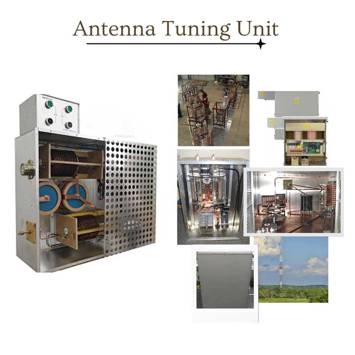
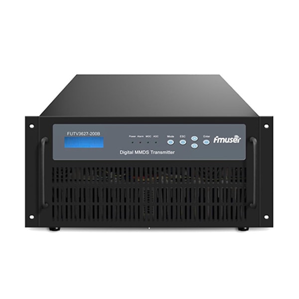
FMUSER 50Ω Solid-state Antenna Tuning Unit for 530-1,700 kHz AM Medium Wave Transmitter Station
FEATURES
- Price (USD): Contact for more
- Qty (PCS): 1
- Shipping (USD): Contact for more
- Total (USD): Contact for more
- Shipping Method: DHL, FedEx, UPS, EMS, By Sea, By Air
- Payment: TT(Bank Transfer), Western Union, Paypal, Payoneer
Quick View
- Tech Spec of FMUSER Antenna Tuning Unit
- Main features of FMUSER Antenna Tuning Unit
- Where to Buy the Best AM Tuning Unit?
- Antenna Tuning Unit: What it is and How does it Work?
- What is the Basic Structure of an Antenna Tuning Unit
- Why ATU is Important for Medium Wave Broadcasting?
Tech Spec of FMUSER Antenna Tuning Unit
| Terms | Specs |
|---|---|
| Operating frequency | 531-1700 kHz medium wave (MW) full band |
| Transmitter Max. Input Power | 1KW/5KW/50KW (based on your need) |
| Passband bandwidth | 25 kHz-30 kHz (half-power bandwidth) |
| Transition belt bandwidth | 30 kHz-80 kHz |
| Stopband bandwidth | ≥100 kHz |
| Antenna standing wave ratio | within ±5 kHz≤1.05, within ±10 kHz≤1.3 |
| Stopband blocking | When the frequency is 100 kHz away from the center frequency, the attenuation is 25 dB |
| Lightning protection | the residual energy of lightning is less than 200 mJ |
Main features of FMUSER Antenna Tuning Unit
- The antenna tuning unit can be applied to one tower single frequency, dual frequency, and triple frequency, as well as medium wave transmitters of various power levels.
- Unique electromagnetic coupling isolation lightning protection technology, in addition to the traditional ground inductance lightning protection, capacitive isolation lightning protection, and graphite discharge spherical magnetic ring lightning protection, the last stage of the network also adds electromagnetic coupling isolation lightning protection, because it is not a traditional device The direct contact conduction and precise frequency selection characteristics make it impossible for the energy of lightning to be directly transmitted to the transmitter through the antenna network. The design of this series of network products adopts the combination of traditional network design and electromagnetic coupling isolation technology, including traditional L-type, π-type design, and traditional lightning protection design, as well as new electromagnetic coupling isolation. Since 2014, it has been widely used in applications and has been well received by users. So far, there has been no transmitter failure caused by lightning, nor a single air conditioning network failure.
- Using single-chip control, the step value of inductance adjustment can be 0.1uH, and the adjustment precision is high.
- Wireless transmission, and the "control box" and "tuning box" are designed with lightning protection to maximize the reliability of control.
- The adjustable range of the coil is close to 10uH, and the range of matching and detuning is also very wide (the tested VSWR within 1.5 can be well matched to 50Ω).
- Equipped with over-adjustment protection, there is no need to worry about damage to the coil caused by misoperation.
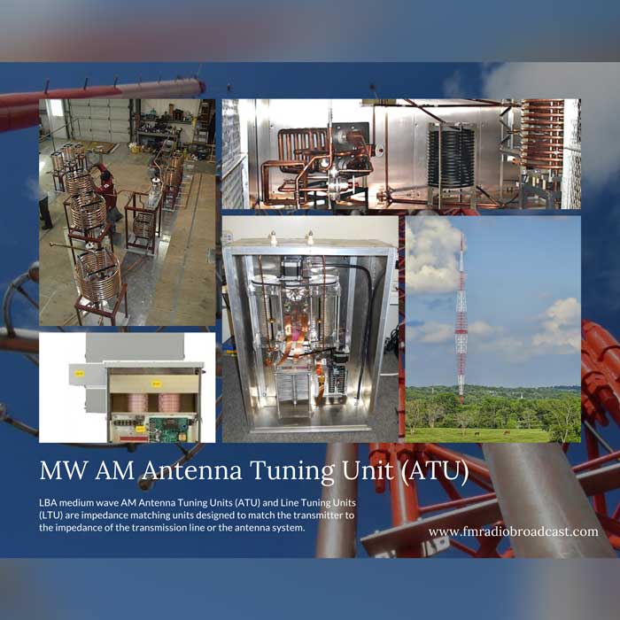
FMUSER: Best Manufacturer of AM Antenna Tuning Unit from China

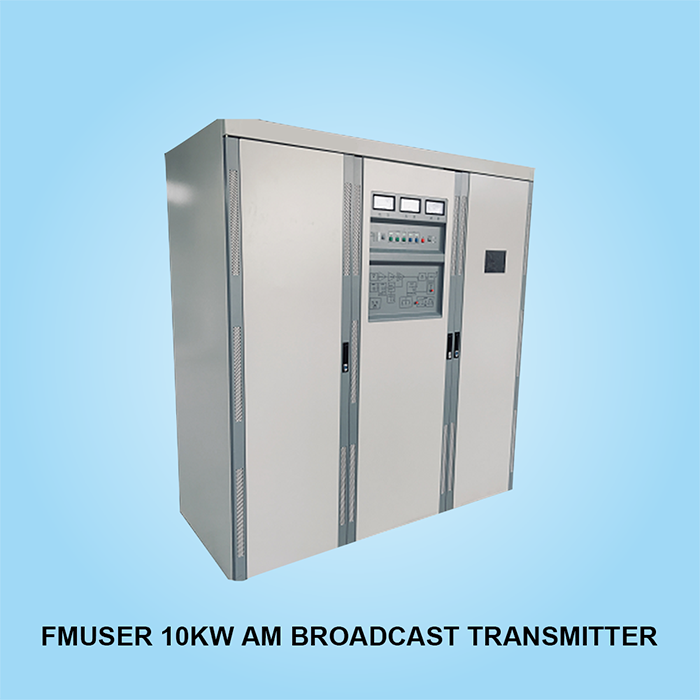
FMUSER is one of the largest AM broadcasting equipment manufacturers and suppliers in China. We provide professional AM (LW/SW/MW) broadcasting equipment and complete turnkey solutions for AM broadcasting stations, including the sale of medium wave transmitters, 50Ω MW antenna tuning unit (input power depends on your AM transmitter power), and several high-quality AM broadcast antennas, dummy loads and other professional equipment.
Watch our 10kW AM transmitter on-site construction video series in Cabanatuan, Philippines:
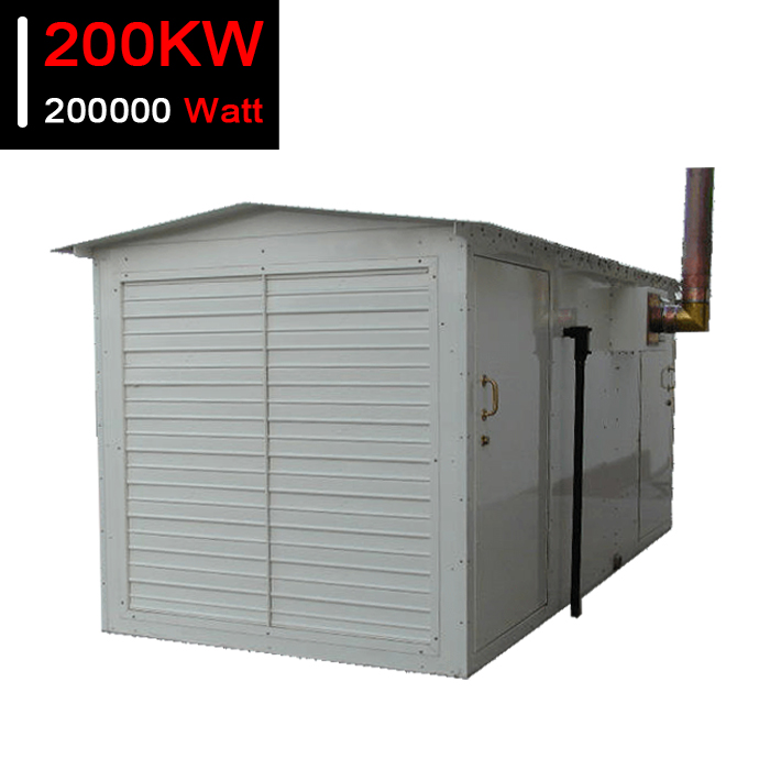
We can provide customized prefabricated buildings for high-power antenna matching units. These buildings use a quick installation system, which can be completely dismantled for container transportation. They are foam insulated, contain RF shielding, can be equipped with a complete electrical system that meets any local standards, and can include heating/air conditioning systems.
The use of these buildings greatly shortens the on-site commissioning time. The building was installed and tested in the FMUSER factory and the antenna tuning system module was installed. Then, the whole antenna tuning unit is marked and recorded for quick assembly at the customer's site before container shipment.
You can provide various accessories and options for our antenna matching unit, or upgrade or repair your existing system. These include mica and vacuum capacitors, high-power components, RF inductors and coils, RF ammeters, tower insulators, lighting transformers, lighting chokes, and cabinets.
Typical services provided:
- Site Assessment And Investigation
- Antenna And Rf System Design
- Project Management
- Installation Supervision
- Troubleshooting And Maintenance
- Maintenance Inspection
- Antenna System Test
- Electromagnetic Hazard Test
Ask for a quotation today and let us help you build your AM radio station!
Recommended Products You May Also be Interested In
| High Power Solid-state AM Transmitters Up to 200 kW |
|||
 |
 |
 |
 |
| 1KW AM Transmitter | 3KW AM Transmitter | 5KW AM Transmitter | 10KW AM Transmitter |
 |
 |
 |
 |
| 25KW AM Transmitter | 50KW AM Transmitter | 100KW AM Transmitter | 200KW AM Transmitter |
| The AM Tower Antenna Test Loads |
||
 |
 |
 |
| 1, 3, 10KW AM test load | 100KW AM transmitter test load | 200KW AM transmitter test load |
Medium Wave AM Antenna Tuning Unit: What it is and How does it Work?
The medium wave antenna tuning unit (ATU) refers to a piece of coupling equipment between the AM broadcast transmitter and the AM broadcast antenna.
The carrier generated by the AM broadcast transmitter is transmitted to the antenna through the coax feeder, and the antenna radiates out electromagnetic waves.
The antenna tuning unit is also named as follows:
- Antenna tuner
- Automatic antenna tuner
- Antenna tuning
- Antenna match
- Ant tuner
- Antenna ATU
- Antenna matcher
- Antenna matching unit
- Antenna tuning unit
- Antenna unit
- ATU antenna
- ATU antenna tuner
- Auto antenna tuner
- AM antenna tuning unit
- Antenna impedance matching network
- ATU antenna tuning unit
Antenna Tuning Unit Design: Explained by FMUSER
The automatic antenna tuner is the bridge that connects the coax feeder, transmitter, and the antenna, by adjusting the transmission parameters, an antenna tuning unit is able to seamless achieve the same impedance between the input end of the transmitting antenna and the feeder and compensating the reactance of the transmitting antenna.

In fact, in the transmitter antenna feeder system, the antenna and the feeder are two systems.
Due to the different impedance characteristics, a part of the electromagnetic energy is reflected back to form a standing wave on the line. The ratio of the voltage peak to the voltage trough of the standing wave is called the voltage standing wave ratio.
When the standing wave ratio is equal to 1, it means that the antenna and the feeder are completely matched, and the high-frequency energy of the transmitter is all radiated by the antenna. The degree of matching between the antenna and the feeder is measured by the reflection coefficient or the standing wave ratio of the antenna input.
For the transmitting antenna, if the antenna tuning is not good, the radiated power of the antenna will decrease, the loss of the feeder will increase, and the power capacity of the feeder will also decrease.
The ratio of the signal voltage to the signal current at the input of the antenna is called the input impedance of the antenna. The input impedance has a resistive component R and a reactive component X, that is, impedance Z=R+JX.
The existence of the reactive component will reduce the extraction of signal power from the antenna from the feeder. Therefore, the reactive component must be made as zero as possible, that is, the input impedance of the antenna should be made as pure resistance as possible.
Therefore, an antenna matching unit is added between the antenna and the feeder.
Looking for more equipment to build up a complete antenna system for your broadcast station? Check these!
 |
 |
 |
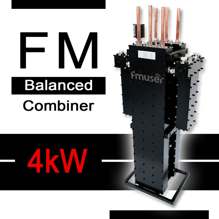 |
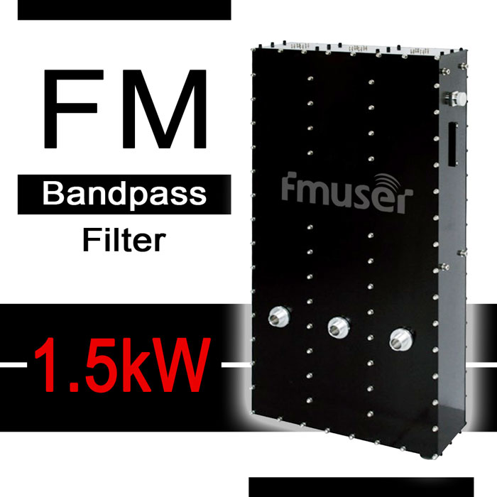
| Coax Connectors | Rigid Line & Parts | RF Cavity Filters | Transmitter Combiners |
 |
 |
 |
 |
| RF Dummy Loads | Lightning Protection | FM Antennas | FM Transmitters |
 |
 |
 |
 |
| AM Transmitters | AM Antennas | TV Transmitters | TV Antennas |
If the impedance characteristic of the feeder is 50 Ω, by adjusting the antenna impedance, the imaginary part of the input impedance is small and the real part is close to 50 Ω within the required operating frequency range so that the input impedance of the antenna is Z=R=50 Ω, and good impedance matching between the antenna and the feeder is achieved. In actual testing, we generally use a vector network analyzer to measure impedance.
The purpose of setting the antenna matching unit is to reduce the standing wave ratio, reduce the reflected power, improve the transmission efficiency, or improve the transmission efficiency.
To adjust the AM antenna tuning unit, on the one hand, the antenna should be in a resonant state, and on the other hand, the impedance of the antenna should be matched with the transmission feeder after being transformed by the matching network.
Of course, even a well-designed and tuned antenna will always have a small reactive component value in its input impedance.
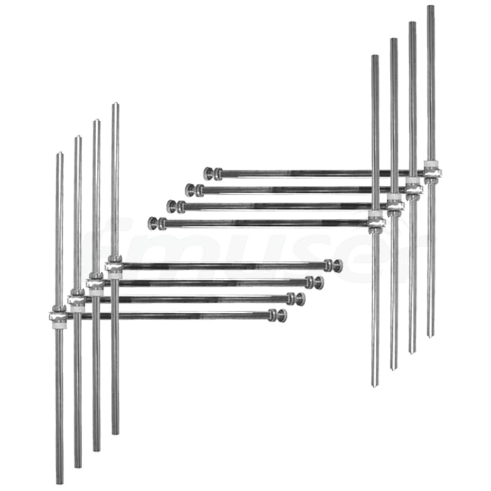
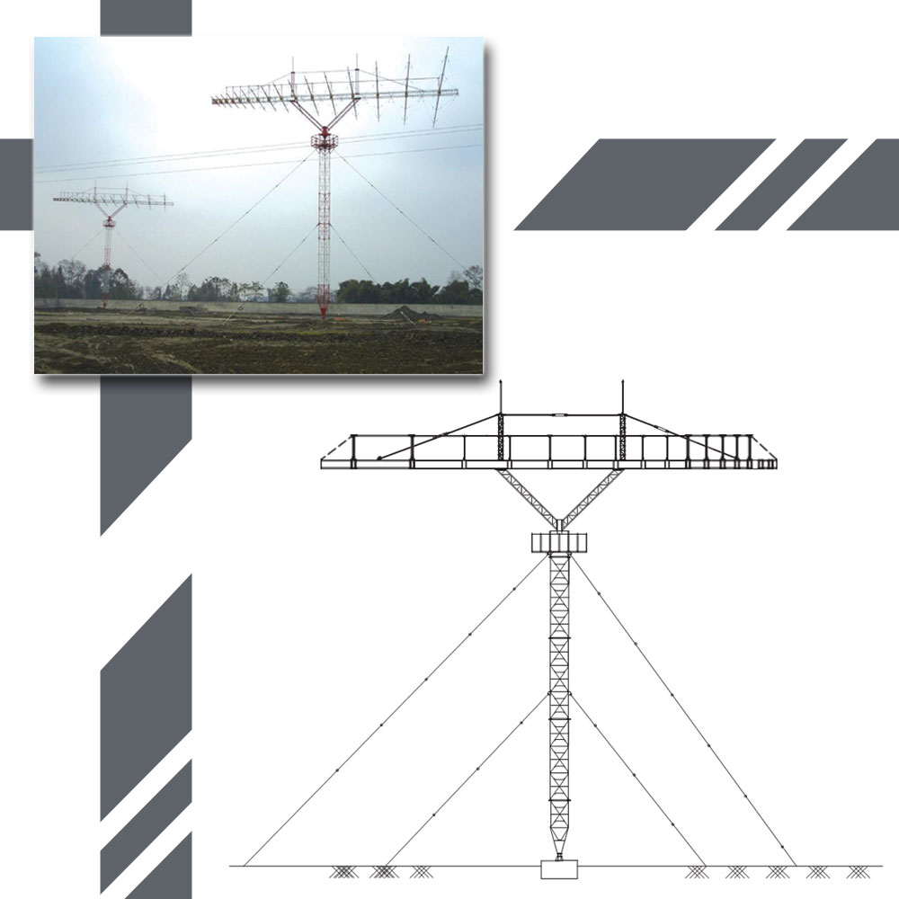
Recommended AM Transmitter Antennas for Antenna Tuning Unit
|
FMUSER Shortwave (SW) Antenna Solutions |
||
 |
 |
 |
| Omin-quadrant SW Ant | SW Omni-multi-fed Ant | SW Rotatable Ant |
 |
 |
 |
| SW Rotatable Curtain Arrays | SW Curtain Arrays HRS 8/4/H | SW Cage Antenna |
 |
 |
 |
| SW Curtain Arrays HRS 4/4/H |
SW Curtain Arrays HRS 4/2/H |
SW Curtain Arrays HR 2/1/H |
 |
FMUSER shortwave transmitter antenna solutions - Visit for more | |
| SW Curtain Arrays HR 2/2/H |
||
|
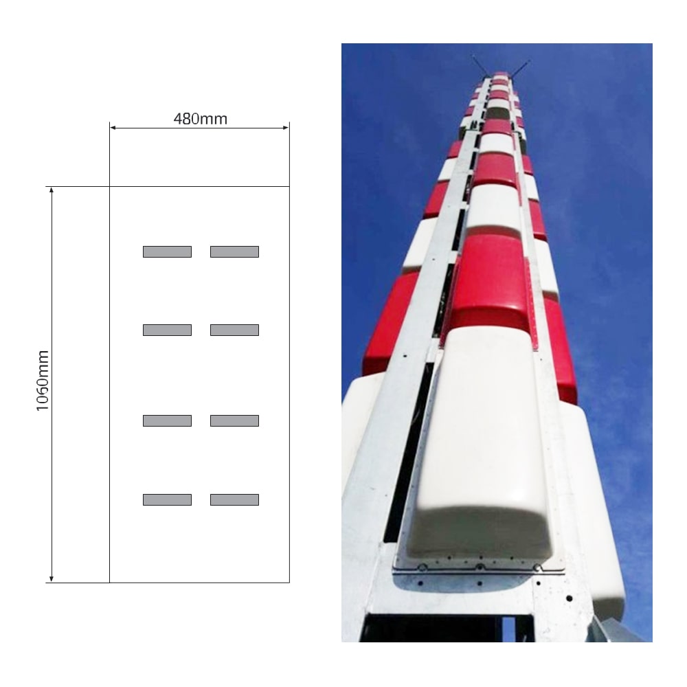
FMUSER Medium Wave (MW) Antenna Solutions |
||
 |
 |
 |
| Receiving Omni MW Ant | MW Shunt Fed Ant | Directional MW Ant |
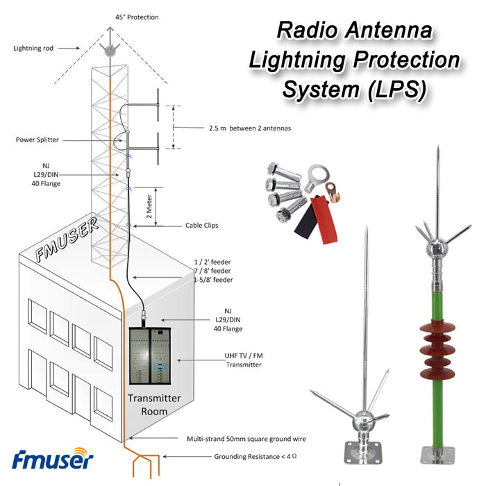
Why Antenna Tuning Unit is Important for Medium Wave Broadcasting?
Generally speaking, a medium wave transmitter station consists of the following typical transmission equipment:
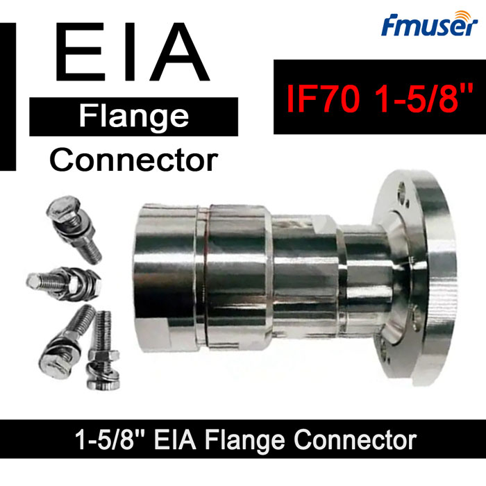
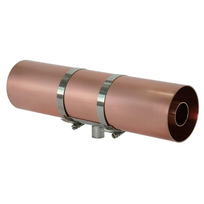
- Brass hard feed tube
- Various feeders and connectors
- medium wave transmitter
- Medium wave antenna tower
- MW Antenna Dummy Load
- Antenna matching unit
Among them, the main functions of the antenna tuning unit are:
- High-frequency feedback suppression
- Impedance matching
- Lightning protection
The equipment in the transmitter room includes brass hard feed pipes, various feeders and connectors, and medium wave transmitters, while the medium wave antenna tower and the AM antenna tuning unit are generally installed outdoors (the antenna adjustment network system can also be installed in inside the wave transmitter).
Antenna Tuning Unit is Born for the Changing MW Transmission Conditions
Due to the more stable environmental conditions, the maintenance of indoor equipment is relatively easy to carry out, while the maintenance of outdoor medium-wave transmission equipment is more difficult, especially the installation and commissioning of medium-wave antennas and ATU antenna tuning units - stemming from this work Most of them are carried out in an outdoor environment, so the working environment will be relatively poor and the maintenance difficulty factor will be relatively high.
In addition, with the development of the city, the antenna network is easily destroyed, the surrounding electromagnetic environment has become more complex, and the number of transmitters due to the failure of the antenna and feeder has also increased. The frequency of debugging networks has become more and more frequent than before.
The Antenna Tuning Unit is the Ultimate Network for a Transmitter Station
It is worth mentioning that the input impedance of the antenna is often related to its geometric structure and the frequency of the incoming radio waves. Here, a set of antenna tuning units that match the input impedance of the antenna and the characteristic impedance of the feeder is required to enable the transmitter output. The high-frequency power can be delivered to the antenna normally.
At the same time, as the ultimate network of the transmitter system, the ATU antenna tuning unit is not only related to whether the transmitter can be turned on normally, but also to the quality and safety of the signal transmitted by the transmitter. Once it is difficult to repair the fault, it will cause the radio station to stop for a long time. broadcast (and in fact, this often happens), which will irreversibly damage the radio station's revenue.
A Good Maintenance of the Antenna Tuning Unit is Critical
The smooth installation, debugging, and protection of the antenna network system are very important for each launch station.
Due to various objective conditions, the medium wave transmitter room in many countries/regions cannot build a matching room, and can only use a matching box. Common matching box installation requirements are:
- The size of the box should be appropriate for the location to be installed.
- When stratifying the internal space of the box, consider the size of the required inductor and allow it to be installed.
- Due to the long-term work outdoors, it is necessary to consider that the box material should be waterproof, fireproof, rust-proof, dust-proof, and sturdy.
- The total weight of the box should be suitable for installation and consider the load-bearing of the pole.
- The box door should be detachable as far as possible for measurement and debugging, and the box door can be opened on both the front and back when conditions permit.
However, the use of matching boxes will greatly restrict the number of components to be placed. There are not many components and limited placement space, and the distribution parameters are complex, which increases the difficulty of installation, debugging, and maintenance.
Recommended Products You May Also be Interested In
 |
 |
 |
|
Up to 1000 Watts |
Up to 10000 Watts |
Transmitters, antennas, cables |
 |
 |
 |
|
Radio studio, transmitter station |
STL TX, RX, and antenna |
1 to 8 bays FM antenna packages |
Antenna Tuning Unit: a Better Solution for Traditional Antenna Tuning
The machine output network of traditional transmitters cannot meet daily needs
With the rapid development of technology in the broadcasting industry, the medium wave transmitter has gradually applied some modern technologies, which not only meet the operating requirements of the transmitter but also greatly improve work efficiency. As a product of the new era, the all-solid-state medium wave transmitter has the advantages of environmental protection and low energy consumption.
At present, the medium wave broadcast transmitter is the most widely used in the TV broadcasting industry. It greatly reduces the cost of maintenance and protection of the transmitter and reduces the consumption of resources and the work of related staff. burden.
It has to be said that a major breakthrough in medium wave transmission technology is the research and use of 10kw all-solid-state medium wave broadcast transmitters. Compared with the previous medium wave transmitter, the operation efficiency of the device has been greatly improved and the maintenance is more convenient, which ensures the smooth operation of the entire system.
The traditional transmitter-side adjustment uses the output network of the machine to match the detuned antenna network, which not only increases the transmission loss but also cannot guarantee the normal operation of the machine.
Although the current all-solid-state medium wave transmitter adopts the integrated precision circuit design, the requirements for the working environment are improved, and the self-protection and monitoring capabilities of the transmitter are enhanced. With a slight change, the transmitter will frequently drop power or automatically shut down.
An Unperfect Design of Medium Wave Transmitter
Moreover, because the anti-interference ability and low voltage resistance of the metal oxide semiconductor field effect transistor used in the all-solid-state medium wave transmitter are not good enough, it will inevitably have a bad influence on the antenna network during the operation.
Whether the transmitter can transmit stably and reliably and achieve the maximum transmission power is largely affected by the design of the antenna tuning unit.
The emergence of the adaptive network has changed the traditional antenna-feeder system with matching and detuning at the transmitter end. When the antenna impedance changes with temperature or humidity, the input impedance of the antenna adjustment network deviates from 50Ω. By adjusting the adaptive network, The impedance of the antenna tuning unit is re-matched to 50Ω, so as to ensure that the transmitter achieves the best transmission effect.
Since the adaptive network is a non-contact adjustment, the adjustment does not affect the normal broadcast of the transmitter, and there is no phenomenon that adjustment is difficult or impossible to adjust after several times of adjustments.
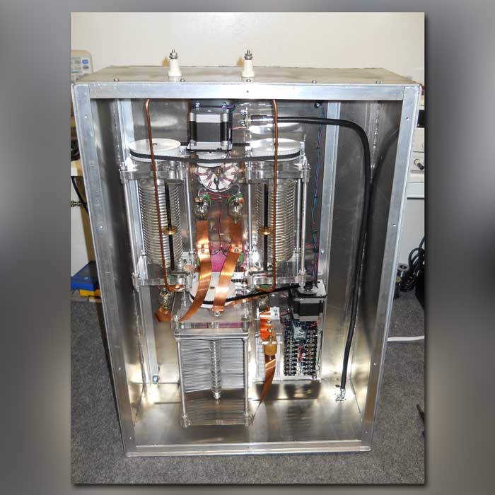
What is the Basic Structure of an Antenna Tuning Unit
The antenna tuning unit is mainly composed of a matching network, blocking network, absorption network, preset network, lightning protection system, and other parts.
In practical applications, because the medium wave antenna is relatively high, it is easily affected by lightning and electromagnetic environment. In order to ensure the safety and normal operation of the transmitter, some suppliers of the antenna network will place graphite discharge balls at the entrance of the antenna for discharge. Or add a blocking network and lightning protection system to the matching network.
Matching Network of Antenna ATU
The significance of the existence of the matching network is to make the all-solid-state medium-wave broadcast transmitter and the feeder characteristic resistance closely connected so that it can find the network settings in the matching state. The matching network has no effect on the smooth operation of the all-solid-state medium-wave broadcast transmitter. underestimated effect.
The antenna matching unit is a network set for seamless connection between the transmitter of the medium wave transmitter and the characteristic resistance of the feeder, and the network is set in a matching state so that the entire transmitter of the medium wave transmitter can be in a good operation state.
The purpose of adding a matching network to the antenna feeder system is to make the impedance of the antenna and the impedance of the feeder equal or similar. There are three forms of matching network: Γ shape, T shape, and Π shape, of which Γ shape is divided into positive Γ shape and inverted Γ shape.
The Γ-shaped network is relatively simple, with only two (two groups) components, an inductor, and a capacitor. In theory, the Γ-shaped network can match any impedance to the impedance we need. The Π-shaped network consists of three components, and the inductance or capacitance of the series arm is regarded as the series connection of two inductances or capacitors, then the Π-shaped network can be regarded as a series connection of an inverted Γ and a positive Γ network. In general design, it is required to choose a form with a simpler structure as much as possible to facilitate debugging. When the input impedance of the antenna is R<Z0 (feeder impedance), the positive Γ shape is selected; when R>Z0 (feeder impedance), the inverted Γ shape is selected.
The Γ-shaped network is relatively simple, with only two (two groups) components, an inductor, and a capacitor. In theory, the Γ-shaped network can match any impedance to the impedance we need. The Π-shaped network consists of three components, and the inductance or capacitance of the series arm is regarded as the series connection of two inductances or capacitors, then the Π-shaped network can be regarded as a series connection of an inverted Γ and a positive Γ network. In general design, it is required to choose a form with a simpler structure as much as possible to facilitate debugging. When the input impedance of the antenna is R<Z0 (feeder impedance), the positive Γ shape is selected; when R>Z0 (feeder impedance), the inverted Γ shape is selected.
Blocking Network of Antenna ATU
The reason why there is a blocking network is that the transmitting antenna of the medium wave transmitting station has a characteristic of reciprocity.
In essence, the antenna matching unit belongs to both the transmitting antenna and the receiving antenna, and generally, the transmitting station does not have only one transmitting antenna and frequency, so the antenna is prone to high-frequency feedback, and the high-frequency signal nearby is received in the reverse direction. In the mixing room, the high-frequency voltage is reversely transmitted to the transmitter through the antenna network and feeder. With the influx of high-frequency voltage, the waveform will inevitably change, the quality of the transmitted signal will be reduced, and it will also affect the transmitter. Equipment and security play out.
The blocking network eliminates the mutual interference between the dual-frequency circuits and improves the signal output quality through the parallel connection of the resonant circuits.
In summary, the effects of blocking the network are:
- through this frequency signal
- Block other frequency signals
When passing the signal of this frequency, the impedance should not be too large. When blocking the signal of another frequency, not only a large impedance should be presented at the other frequency, but also a large impedance should be presented at the upper and lower side frequencies of the other frequency, blocking the unnecessary frequency. frequency.
Absorption Network of Antenna ATU
The significance of the existence of the absorption network is to reduce the voltage rise rate of the circuit and prevent the overvoltage at both ends of the capacitor from damaging the equipment and causing failures.
Pre-tuned network of Antenna ATU
The pre-adjustment network is to match the antenna impedance, mainly by adding an inductance at the bottom of the antenna and the antenna impedance in parallel to form a suitable real part of the reactance to facilitate the design and debugging of the matching network.
CONTACT US


FMUSER INTERNATIONAL GROUP LIMITED.
We are always providing our customers with reliable products and considerate services.
If you would like to keep touch with us directly, please go to contact us
-
![Home]()
Home
-
![Tel]()
Tel
-
![Email]()
Email
-
![Contact]()
Contact


